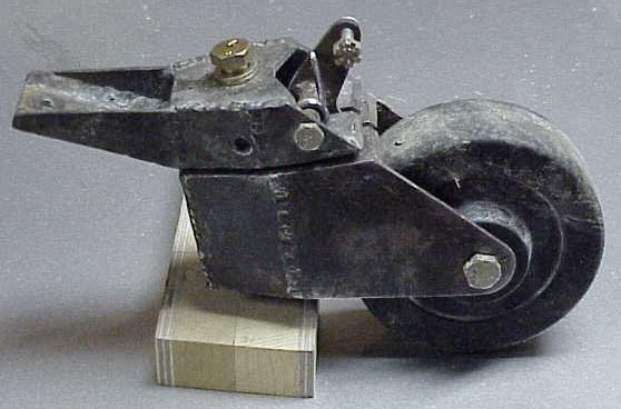
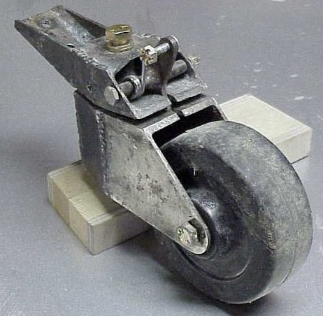
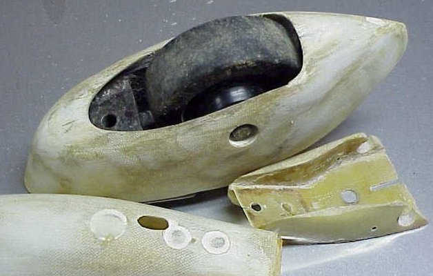
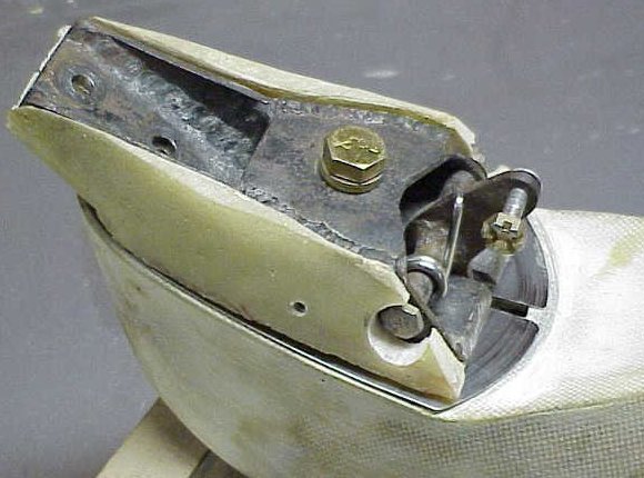
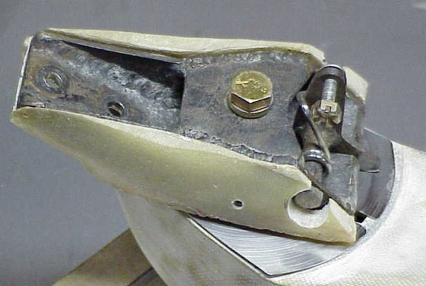
An overall view. The wheel is from an industrial swiveling dolly. The locking lever is "L" shaped. When locked, it is in a slot in the lower portion. When pulled forward, the level retracts from the slot and the tailwheel is free to swivel.
The horizontal pieces are 0.125" thick and the vertical ones are 0.090". The entire assembly, complete with a cutdown truck spring and fairing, is lighter than a Scott tailwheel from a Cessna 120
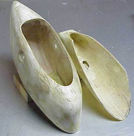
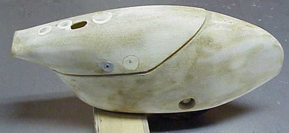
The lower portion of the tailwheel assembly was covered with duct tape and then two plies of glass. This became the interior of the fairing. Foam was glued over that glass, shaped, and then covered with three plies of glass.
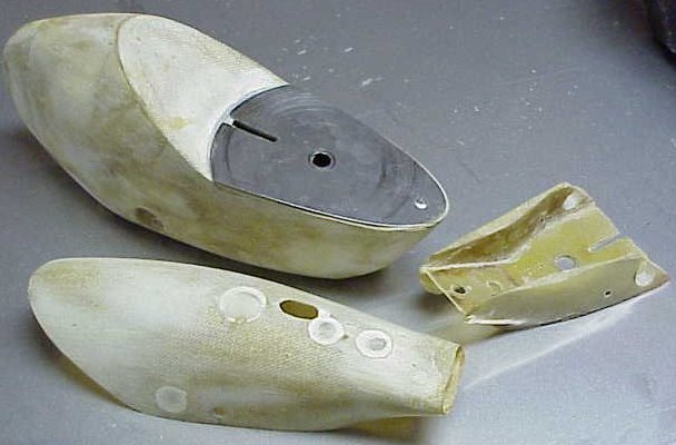
The shield is a thin piece of stainless steel. It prevents the locking level from cutting through the fiberglass that is on top of the lower assembly. The support for the upper portion of the fairing cover was made by covering the upper portion of the tailwheel assembly with duct tape and then glass. More duct tape covered the inside of the tailwheel fairing, and flox filled the cavity that remained. It was shaped and worked until it fit very nicely.
The tailwheel bolt and the swivel bolt hold the bottom portion in place. The bolt holes were finished off by covering a wrench socket with duct tape. A bit of foam was removed from around the bolt, and the void was filled with flox.
A future addition will be a hook at the front of the lower portion of the tailwheel. I am planning on hand-proping. The hook will hold a tie down rope until the tail wheel is released. This is similar to using a glider tow release but will be lighter since it combines two functions in one.