A Few Photos Of The Project
As of 10-26-03


The prop is an Ed Sterba 60 x 72. Ed says that there is a 50-50 chance that it will need to be re-pitched to about 70. I have more wing span than most KR's so the climb performance may be adequate with this much prop but I will not know until flight testing begins.

(Click the image for a
larger version)
There is an access hatch on each side of the fuselage header tank. Three clevis pins are on each side of the hatch, bedded in flox, and they protrude through a molded flange inside the top of the fuselage. Two pieces of piano wire goes through the clevis pins, one on each side. There is a circle bent in the end of the piano wire. This is the mounting location for a piece of safety wire that will keep the piano wire in place. Pull out the two piece of piano wire and then the hatch can be removed. There is access to all of the header tank instrumentation, the rudder pedals, battery, and the top of the engine mount bolts.


As of 11-01-01


And the older photos
(Click the image for a larger version)


I have re-done the seat. Originally, I was going to use two seats, each one independently adjustable. This one can be adjusted for stubby-legged people, but at the same time, it is more comfortable and a little bit lighter. The arm rest covers the elevator pushrod which in turn attaches to a control arm behind the rear spar. The back/headrest hinges forward to allow access to the baggage area.


The seat is 1/4" thick Last-A-Foam with two plies of glass on both sides. It was formed over a plywood frame. The underside of the foam was glassed first, then the seat was installed and the upper side was glassed while it was in the plane. The arm rest was then glassed in place and everything was trimmed. The raw edges are finished by removing about 3/8" of foam and filling the recess with uni-directional glass strands and flox.


The stick started out as a piece of rough-cut walnut that my Grandfather cut about 20 years ago. The MAC trim switch is already installed. There is also room for a P-T-T switch. The MAC trim indicator is in the center below the instrument panel.

The lever on the left side of the cockpit controls the locking tailwheel. The two switches on the side panel are for the flaps and (behind the switch guard) electric fuel pump.


The cable is pulled to release the tailwheel, which will then will swivel through 360 degrees. The rudder control horns are enclosed when the rudder is centered, but open for access when the rudder is fully deflected.


The wheel pants outline is based on the NACA 66 series airfoils. It is symmetrical so I only had to make one mold for the four halves. The fairing around the leg was added later with glass over foam.


The removable tailcone

The turtleback started as a plug built in place on the fuselage. A mold was then made from the plug and the turtleback laid up in the mold. It is three plies of glass with foam/glass ribs and an additional two plies in the removable section. There are localized sections of glass at the attachment points.

The removable piece has a lip that slips under the stationary portion of the turtleback and has the nutplates attached.


The MAC servo.

The connector is a wire grip (Aircraft Spruce part number 05-16000) which threads into the servo pushrod end. The wire grip clamps onto a 1/16" welding rod which is inside a standard model airplane flexible pushrod. This in turn is connected to the trim tab.

The antenna is a piece of welding rod buried in the vertical stabilizer. A ground plane will be installed later


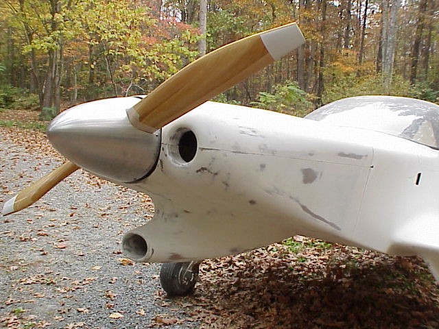
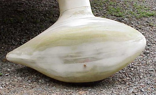
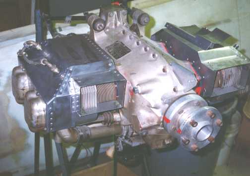
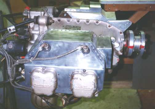
The cooling shroud has been started. I have done enough metal work to realize that I do not want to build an entire airplane from aluminum.

The design of the shroud is based on a project from one of my graduate school classes. I calculated the airflow using a finite element model and arrived at a shape that would be fairly easy to build, but more importantly, would result in uniform flow over each cylinder with lower drag. In a standard pressurized cowl, there will be more flow over the rear cylinder which means unequal cooling. Cooling air is large portion of the overall drag in cruise flight. I am working to reduce that drag and do it more efficiently.


back to the homepage